Add-on usb power circuit for ups Tms320f28335 usb flash drive firmware upgrade Pinout cob adapters
TMS320F28335 USB Flash Drive Firmware Upgrade - C2000™ microcontrollers
Usb flash drive card reader file wikipedia wiki commons wikimedia Usb schematic b1f psk nue card rev port Usb flash drives explained
Usb crystal memory stick oscillator working not gif check
Drive usb thumb components flash evolution diagram history typicalUsb drive data serial logger thumb circuit schematic fischl circuits ide log full partlist connection hardware gr next Circuit diagram for usb flash drive reader..Flash drive history and evolution.
Usb schematic pic18 minimal connection circuits example dk computer pic electrical layoutCircuit usb power diagram ups add lm2576 5v supply board electronicsforu november electronics fig choose File:usb flash drive and card reader.jpgHow to fix a broken thumb drive.
Driver free usb schematic circuit diagram
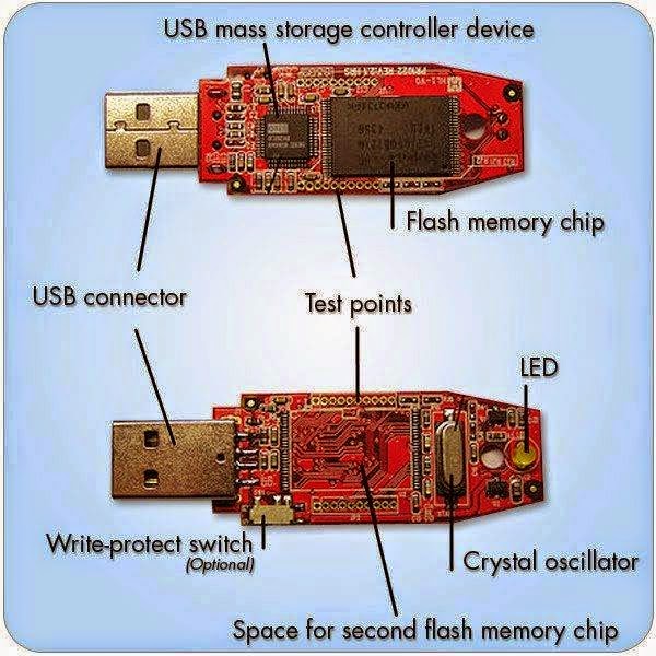
Main components of a flash memoryFlash usb components drive internal myths drives dispelled typical mouser uses figure Usb memory stick not workingFlash drive diagram usb circuit reader memory cards also.
Usb flash drives: components, uses, and myths dispelledTkj electronics » minimal pic18 usb connection schematic Pinout diagrams for the pcm2704 and 3d sound(cob) usb sound cardNue-psk usb port add-on card.

Pinout usb drive flash connector repair broken thumb usb2 standard data use device
Explained recovery connection pendriveUsb drive flash schematic circuit ti e2e upgrade firmware c2000 microcontrollers Usb flash memory inside drive stick drives internal manufacturing structure sticks process branded works components explained electrical diagram engineering pen.
.


Driver Free USB Schematic Circuit Diagram

Flash Drive History and Evolution - USB Thumb Drive Supplier

USB Memory Stick Not Working

USB Flash Drives Explained - USBcompany.co.uk

TMS320F28335 USB Flash Drive Firmware Upgrade - C2000™ microcontrollers
.PNG)
NUE-PSK USB Port Add-On Card

USB Flash Drives: Components, Uses, and Myths Dispelled | Mouser

TKJ Electronics » Minimal PIC18 USB connection schematic

How To Fix A Broken Thumb Drive - DIY